Plotting and piloting
Lines of Position
The modern chart shows us positions of many recognizable navigation
aids like churches and lighthouses, which facilitate the approach to a
coastal area.
This concept originated from a chart by Waghenaer and proved a milestone in the development of European cartography. This work was called “Spieghel der Zeevaerdt”
and included coastal profiles and tidal information much like the
modern chart. It enables us to find the angle between the North and for
example a platform, as seen from our position.
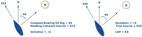
Taking a bearing on this oilrig with a compass provides us with a
compass course. This course first needs correction for both variation
and - via ship's heading -
deviation
before plotting a Line of Position (LOP) in the chart. Our position is somewhere along this line.
Ranges
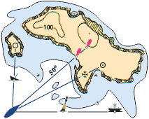
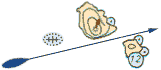
A precise way to obtain a LOP (and without a compass) is to locate two navigational aids in line.
The image on the right shows us four examples of ranges, each consisting of two nav. aids.
Please, note that:
- More distance between the two nav. aids enhances accuracy.
- And less distance between the vessel and the closest nav. aid also enhances accuracy.
One of the four ranges consists of two lights that are intentionally placed to provide a LOP. These pairs of lights are called Range lights or Leading lights. In this case they indicate the channel between the shallows along a true course of 50° .
When looking toward the leading lights, the closest one will be lower.
Therefore, in the middle of the channel both lights will appear above
each other.
Even when there are no man-made structures available, a range can be
found by using natural features such as coastlines and islets.
The example on the left shows a yacht that will avoid the dangerous
wreck as long as the islets don't overlap.
The Position Fix
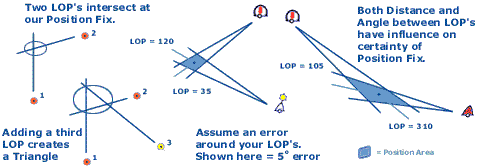
To construct our position fix we need two of these lines of position to intersect each other. Fix is the initial element of the ship's navigational and dead reckoning
(see below) plot. A fix is the ship's position on the earth at some
given point in time. A fix is determined by the simultaneous
intersection of LOP's.
Often however, a triangle occurs when a third LOP is added in the
construction. This indicates that there are errors involved in at least
one of the bearings taken. In practice, we should consider each LOP as
the average bearing in a wider sector of, for instance 10°. Bearings
create more certainty about our position when they are perpendicular to
each other. Yet, bearings on distant objects bring about more
uncertainty in our position fix as the sector widens. If moving fast
you should not put any time between the bearings.
In
the next example we will plot our position fix by taking bearings at
two light vessels just off the coast of Willemsen Land. To plot in the
chart we will use a soft pencil and avoid drawing lines through the
chart symbols. This is to prevent damage to the chart when you have to
erase the construction.
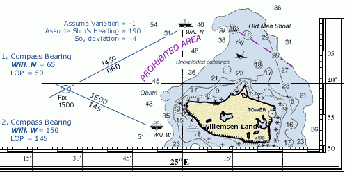
Since we use our steering compass for our
bearings the same deviation table can be used. We will assume the
variation to be -1° and the ship's compass heading 190°. Hence, from
the deviation table we find a deviation of -4°.
The construction:
- The first compass bearing on 'Will. N' is 65°.
cc + var. + dev. = tc, therefore tc = 60°.
- Plot the LOP in the chart aligned to this lightship. Mark 'Time' and 'True Course' along with it.
- Mutatis mutandis the second LOP on 'Will. W' is 145°.
- The
intersection of these two LOP's is our Position Fix. Mark this with an
'Ellipse' and the 'Time'. The greater the uncertainty, the greater the
ellipse (position area).
- Fixed Position around 15h00m = 39° 58'.9 N , 24° 25'.5 E, approximately. So, welcome to my island but mind the rocks!
Although we didn't have a third LOP creating the dreaded triangle, we
still have to doubt the accuracy of our position fix. Then, if three or
more LOP's were used, and a nice point was not achieved, we again are
left with some ambiguity. This could be caused by any number of
reasons, including instrument errors, erroneous identification of a
navigation aid, sloppy plotting, or error by the bearer taker, among
others. In this case, we will assume that we are at the worst possible
position (i.e. closest to the nearest navigational hazard).
To minimize the effect of possible errors the optimum angular spread should be 90° when two objects are shot or 120° when three objects are shot.
The Estimated Position
It is sometimes impossible to obtain more than one LOP at a time. To
determine the ship's position using only one navigation aid, we can use
a running fix (see below). However if a running fix is not possible, we can determine an estimated position.
 An estimated position is based upon whatever incomplete navigational
information is available, such as a single LOP, a series of depth
measurements correlated to charted depths, or a visual observation of
the surroundings. An estimated position can be determined using a
single LOP and the ship's Dead Reckoning Position (DR).
This is done by drawing a line from the DR position at the time of the
LOP perpendicular to the LOP. An EP is denoted by a square instead of
an ellipse used for a fix.
An estimated position is based upon whatever incomplete navigational
information is available, such as a single LOP, a series of depth
measurements correlated to charted depths, or a visual observation of
the surroundings. An estimated position can be determined using a
single LOP and the ship's Dead Reckoning Position (DR).
This is done by drawing a line from the DR position at the time of the
LOP perpendicular to the LOP. An EP is denoted by a square instead of
an ellipse used for a fix.
Do not rely on an EP as much as a fix. The scale of reliability, from best to worst:
- Fix
- Running Fix
- Estimated Position
- DR position
Dead Reckoning
Dead reckoning
is a technique to determine a ship's approximate position by applying
to the last established charted position a vector or series of vectors
representing true courses and speed. This means that if we have an
earlier fix, we plot from that position our course and 'distance
travelled since then' and deduce our current position.
 0930: We start off with a Fix and plot
a DR position for 15 minutes later.
0945: Our estimation about our speed
and course was correct, so we don't have to
charge the DR position.
1000: and so on...
S = Speed through water
C = Course (T = true, M = magnetic, C = compass) through water.
Mark with an arrow as indicated.
Dead reckoning is crucial since it can provide an approximate position
in the future. Each time a fix or running fix is plotted, a vector
representing the ordered course and speed originate from it. The
direction of this course line
represents the ship's true course, and the length represents the
distance one would expect the ship to travel in a given time. This
extrapolation is used as a safety precaution: a predicted DR position
that will place the ship in water 1 meter deep should raise an
eyebrow...
Guide-lines:
- Plot a new course line from each new fix or running fix.
- Never draw a new course line from an EP.
- Plot a DR position every time course or speed changes.
- Also, plot a DR position when a single LOP is obtained.
- Label the DR position with a semi-circle and 'DR'.
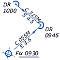
Running Fix
Under some circumstances, such as low visibility, only one line of
position can be obtained at a time. In this event, a line of position
obtained at an earlier time may be advanced to the time of the later
LOP. These two LOP's should not be parallel to each other; remember
that the optimal angular spread is 90°. The position obtained is termed
a running fix because the ship has "run" a certain distance during the
time interval between the two LOP's.
0905:
Our tacking sequence starts with a solid position Fix.
0916:
We obtain a single LOP and construct a corresponding (same time)
dead reckoning position.
Our estimated position is constructed by drawing the shortest line between the DR and the LOP
(perpendicular.
0926:
No LOP's at all.
We tack and construct a DR position.
0934:
We obtain a LOP on Oil Rig 2.
To use the first LOP we advance it over a construction line between the two corresponding DR positions.
We use both its direction and distance.
To use the LOP obtained at the earlier time, we must advance it to the
time of the second LOP. This is done by using the dead reckoning plot.
First, we measure the distance between the two DR positions and draw a construction line, which is parallel to a line connecting the two DR positions.
Note
that if there are no intervening course changes between the two DR
positions, it's easiest just to use the course line itself as the
construction line.
Now, using the parallel rulers we advance the first LOP along this
construction line over the distance we measured. Et Voilá, the
intersection is our RFix.
If there is an intervening course change, it appears to make our
problem harder. Not so! The only DR positions that matter are the two
corresponding with the LOP's.
Advancing a LOP:
- The distance: equal to the distance between the two DR positions.
- The direction: equal to the direction from the first to the second DR position.
- Label the Running Fix with an ellipse and "RFix".
Danger Bearing
Like the dead reckoning positioning the danger bearing is an important tool to keep the ship out of trouble.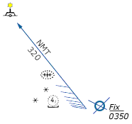 First, the navigator identifies the limits of safe, navigable water and
determines a bearing to a prominent landmark. This bearing is marked as
"No More Than" (NMT) or "No Less Than" (NLT), depending on which side is safe. Hatching is included on the side that is hazardous, along with its compass bearing.
First, the navigator identifies the limits of safe, navigable water and
determines a bearing to a prominent landmark. This bearing is marked as
"No More Than" (NMT) or "No Less Than" (NLT), depending on which side is safe. Hatching is included on the side that is hazardous, along with its compass bearing.
When a distance instead of a direction is used a danger range is plotted much the same way as the danger bearing.
Turn Bearing
The Turn bearing - like the danger bearing - is constructed in the
chart in advance. It should be used as a means of anticipation for
sailing out of safe waters (again like the danger bearing and dead
reckoning). The turn bearing is taken on an appropriate navaid and is
marked 'TB'. As you pass the object its bearing will slowly change. When it reaches the Turn bearing turn the vessel on her new course.
This type of bearing is also used for selecting an anchorage position or diving position.
Snellius Construction
Willebrord Snellius- a 16th century mathematician from Leiden NED - became famous for inventing the loxodrome and his method of triangulation.
The Snellius construction was first used to obtain the length of the meridian by measuring the distance between two Dutch cities .
He took angles from and to church towers of villages in between to
reach his objective. We now can use the Snellius method to derive our
position from three bearings without the use of LOP's. We can leave out
deviation and variation, which simplifies things. Also, since only
relative angles are needed a sextant can be used to measure navigation
aids at greater distances.
.
He took angles from and to church towers of villages in between to
reach his objective. We now can use the Snellius method to derive our
position from three bearings without the use of LOP's. We can leave out
deviation and variation, which simplifies things. Also, since only
relative angles are needed a sextant can be used to measure navigation
aids at greater distances.
The construction:
- Compass bearings are 320° on A, 360° on B and 050° on object C.
- The angle between A and B = 40°.
- The angle between B and C = 50°.
- Draw lines from A to B and from B to C.
- Add the two perpendicular bisectors (yellow) of lines AB and BC.
- Draw at object A a construction line (blue) 40° inland of line AB.
- Draw at object C a second construction line (blue) 50° inland of line CB.
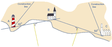
- At object A: draw a new line (red) perpendicular to the construction line.
- At object C: draw another new line (red) perpendicular to the construction line.
- The two intersections of the red and yellow lines indicate the centres of two circles.
- Finally, draw the first circle using A and B and the second circle using B and C.
- The off shore intersection of the two circle gives us our position fix.
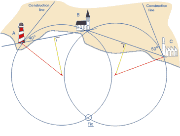
The advantage: deviation and variation can be left out since the angles
(here 40° and 50°) are relative ones. Moreover, a sextant can be used
to obtain angles between objects at greater distances, which with a
compass would be less precise.
Learn sailing and navigation via yacht charters with instruction in Greece.
Notation
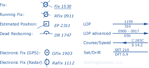
Overview
- Line Of Position (LOP): The locus of
points along which a ship's position must lie. A minimum of two LOP's
are necessary to establish a fix. It is standard practice to use at
least three LOP's when obtaining a fix, to guard against the
possibility of and, in some cases, remove ambiguity.
- Transit fix: The method of lining up charted objects to obtain an LOP.
- Leading lights or Range lights: A pair of lights or day marks deliberately placed to mark a narrow channel.
- Position fix: The intersection of various LOP's.
- Cross bearing: The use of LOP's of several navigational aids to obtain a position fix. Remember to use an optimal angular spread.
- Running fix: The use of an advanced
LOP. Make sure to use only the corresponding DR positions. Also don't
use the EP for advancing the first LOP.
- Dead reckoning: Determining a position
by plotting courses and speeds from a known position. It is also used
to predict when lights become visible or to determine the set and rate
of a current.
- Estimated position: Combine a corresponding DR position with a single LOP to get an EP position.
- Snellius construction: Another way to
combine three compass bearings to obtain a position fix. The advantage
over a cross bearing is that both magnetic variation and deviation
don't need to be taken into account.
- Course: (C) The direction in which a vessel is steered or is intended to be steered (direction through the water).
- Speed: (S) The speed of the boat through the water.
- Set: (SET) The direction in which the current is flowing (see chapters 6,7 and 8).
- Drift: (DFT) The speed (in knots) of the current (see chapters 6,7 and 8).
- Default heading is True course (M = magnetic , C = compass).
- Default time is 24 hour clock ship time else UTC.